Showing posts with label Amplifiers. Show all posts

Monday, 16 December 2019

70cm 250W Amplifier from secondhand DVB-T PA Part Three

You may remember in my first blog post about this amplifier I mentioned I had bought from eBay an LPF for the unit and I was a little worried this wouldn't perform as well as the eBay listing had lead me to believe.

I've finally managed to get hold of a cheap HP 8594e spectrum analyser from a fellow amateur through the second-hand advertisements in the back of RadCom and the seller very kindly included a nice directional coupler in with it, so with spectrum analyser and coupler in hand, I decided after much reading to finally connect it all up with the amplifier and see what the output looked like.

70cm Amplifier Output at 140W
You can see from the above any harmonics that are present are at least -60dBc.   The test was performed using the two tone generator within the Elecraft K3s.

Monday, 9 December 2019

70cm 250W Amplifier from secondhand DVB-T PA Part Two

With the amplifier built the next item on the list was finding a power supply for it.   Originally I was going to use two HP DPS-600PB server supplies in series which would have given around 28V at 55A.

While building the amplifier I had an email from a fellow amateur Steve G4MJW asking what LPF I was using and we have been helping one another out with ideas since.

One of Steve suggestions was to use an old Ericsson 27.2V 55A PSU from a RBS 2216 900MHz GSM station which are / were available on eBay for £28 plus postage.    The nice thing with the Ericsson PSU over the HP server modules was the fact everything was in one unit.  

I couldn't find much information on these PSU however I did find a German website detailing a tear down of the RSB2216 unit including the PSU with a rather handy note that you would adjust one of the trimpots, the one on its own furthest from the three that are in line,  to increase the output voltage to 28.2V from the standard 27.2V.

One thing Steve noticed before me as he ran his for longer than a few minutes was the temperature of the case which was hot to the touch to the point the unit turned itself off.  

I ran mine for and hour and half an in that time the temperature got up to a rather barmy 39 degrees C, so some cooling was in order.  

My original thought was to use some small 30mm fans attached to the rear plate of the unit but in the end I went with two 28V 80mm fans purchased from eBay.  

The fans worked great and in fact I think a single fan would suffice and to be honest two or three 30mm fans on the back would also probably be enough.

With the fans installed the unit now runs cold so a success all in all.

The next thing to do was find a way of connecting equipment to the unit and again Steve came to the rescue when he pointed out he'd bought some banana jack sockets from eBay that by chance happened to have a thread big enough to self tap in the original DC power socket.

All in all modifying the PSU and getting it and running took an afternoon of drilling and filing to fit the fans and 10 minutes to wire it all up.

I have to thank Steve greatly for coming up with this PSU it saved me an awful lot of mucking around and gave a nicer / safer unit than the HP server supplies.

The finished PSU


Tuesday, 26 November 2019

70cm 250W Amplifier from secondhand DVB-T PA Part One

When I last posted in June I mentioned I had bought a secondhand DVB-T PA from a German eBay seller well I've finally got around to putting it all in a box and getting it up and running.

The PA module is simple to modify and in fact I found during an internet search a website by a Dutch amateur PA0EHG who had already modified one of these amplifiers and I followed his instructions which worked perfectly.

The PA is coupled with a LPF again from eBay which looks like it's a based on a design by Jim W6PQL the specifications where 2nd order harmonics -35dB and 3rd order -55dB with an insertion loss less than 0.15dB.

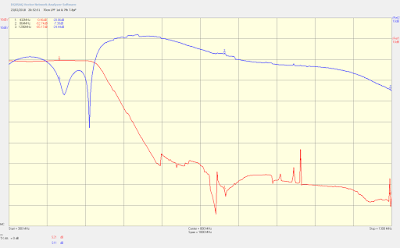
When measured with the VNA I found the 3rd order harmonic weren't rejected as much as specified so I expect it might need another coaxial stub filter to drop the 3rd order harmonic a little more.

70cm eBay LPF filter response.
I put the LPF in a tin box bought from Alan G3NYK though I had to buy a bigger box than was required and trim it down to size using tin snips.

To monitor the amplifier I was going to roll my own controller board but again Jim W6PQL has what he calls the ultimate amplifier controller board which at $50 for a kit I thought was a bit of bargain and a lot less hassle than making my own even if half the features of the board aren't being used.

I stuck all this in a rather large Hammond box so its ended up not being a small amplifier but you go with what you have laying around the shack.

I painted the case in acrylic paint and though the result was good looking I don't hold out much hope for it's long term durability.

Front Panel
Reat Panel
Top View
Internals

The amp requires a quite hefty PSU 31V 17A but more on that in later post.

Friday, 14 June 2019

Just a quick update to say I'm still kicking.

Been a quiet month or so and so I thought I better write something for this blog.  ;-)

First off I got fed up trying to get a clean signal from the Gemini 2-500 PA using the Anglian transverter and Icom 7300.   No matter what I seemed to do I could not stop it from occasionally causing splatter, along with the RF surges in power when first keying the transmitter.    Now this isn't to say the IC7300 is a bad radio it isn't but it certainly doesn't like playing the transverter and Gemini.    So to resolve the issue I went and bought an Elecraft K3S which has resolved all the issues and ok it's an expensive fix but the transmitter of the K3S is certainly worlds ahead of the IC7300, though I do still prefer the audio from the 7300 which is much easier on the ears.  

One of the nice things about using the K3S is the fact it displays the right frequency when using the transverters and in fact with in a few days of having it I also discovered it out from TTL logic from the ACC port so you can interface some kind of transverter switching.    

With the above in mind I wondered if a simple transverter switch and device sequencer could be bought and though I did find a couple they were quiet expensive so I decided to roll my own using an Arduino so a couple of prototypes later I've come up with a design with will switch between my 2m and 70cm transverters and handle the device sequencing for both units below is a couple of screenshots from KiCad of the front panel indicator and main board.  I'll do a full write up once I've confirmed all works as expected.  

A quick feature list is as follows.


  1. Handles two transverter. 
  2. Provides TX inhibit. 
  3. First sequence event can provide 12 - 28V up to a couple of amps to drive change over relays.
  4. Sequence events two and three can sink up to 40mA, though you could chuck in a darlington pair if you want to sequence more relays.
  5. The unit interfaces with my Wavenode so that if a high VSWR is seen the unit automatically ceases transmitting and puts the unit into the default RX mode.
  6. All sequence event are optocoupled to the Arduino just in case a FET or BJT decides to go legs up in a funny way.
Front panel layout from KiCad
Main board layout from KiCad.

I've also got another project on the go in the form of a 70cm 250W amplifier which I bought from eBay from a German amateur which was quite cheap at 55 Euros.  

70cm 250W PA module from eBay.
I rather helpfully came across the website of PA0EHG who had bought the same unit and documented what he had done to get the unit going on the 70cm band so once I've got a replacement RF terminator as the one that came with the unit the solder tab fell off as soon as I touched it I'll power it and see what's what.

So that's the end of this update I'll do a proper update once everything has progressed a bit further.


Tuesday, 15 May 2018

Cheap Chinese 70cm 100W Linear Amplifier - Part 3

I've had quite a bit on lately finishing the Iceni and Anglian transverters by G4DDK but I managed to find some time to do a bit more to the 70cm PA.

Using the same setup as the last time I tested the harmonic output I got the following results.

2nd Harmonic was at -38dBc originally measured at -40dBc

and the

3rd Harmonic was at -68dBc originally measured at -53dBc

So not the big improvement I was hoping for and in fact 2dB worse for the second harmonic.

I tried running the unit with a lower drive giving an output of 50W and in fact the 2nd harmonic got worse as well as at various other lower drive levels.

I've yet to decide how to rectify that small problem I could use a small mini-kits LPF from Australia or the cheap way a 1/4 wave stub notch filter cut for the 2nd harmonic.

The other thing I've discovered is to not pick the PA up after running a CW test as the heatsink gets mighty hot. ;-)

Wednesday, 14 March 2018

Cheap Chinese 70cm 100W Linear Amplifier - Part 2

I finally got my VNWA back from sdr-kits after receiving a DOA unit and then I found I had a faulty calibration cable as well, all of which was resolved quickly with no aggravations, so I had another look at the 70cm PA's LPF.

Though the original filter looked good on the old VNWA but I thought I'd better check with the new one just to be certain of the results.

Though the filter still looked fairly good I decided to adjust the inductor size slightly.  The original designed called for each coil to be wound on a 3mm mandrel for two turns so I increased the mandrel size to 3.2mm which yielded worse results but gave me some adjustment in the coils unlike the original.

The insertion loss stayed almost the same at 0.43dB but the return loss was improved by almost 10dB and the second harmonic was also improved by almost 10dB.    So the VSWR is now around 1.07:1 down from 1.2:1 originally.

LPF with increased coil diameters.
Now I just need to arrange to take the unit over to my friends with the spectrum analyser and see how the modifications have worked. 

Part Three coming soon. 

Saturday, 3 March 2018

Cheap Chinese 70cm 100W Linear Amplifier - Part 1

Wanting to dip my toes deeper into 70cm I decided in December I could do with a little more power than the 50W my Yaesu FT991 puts out and decided a 100W linear was the order of the day.

After looking around on the Internet and various UK suppliers I headed to the drinks cabinet for a stiff whisky after balking at the £400+ price tags and decided a homebrew amp was in order.

A quick Google later and I came across an A/B class linear on eBay, from our friendly cousins in China, based on the Motorola MRF186 for £28.99 inc P&P and promptly ordered the kit, which according the advertisement was 100% brand new.  Two weeks later the kit dropped through the door to say I was impressed is an understatement.

Opening the package up I found a good quality PCB and assorted components however upon closer inspection found the MRF186 was actually second hand along with the High Q capacitors, but otherwise everything looked OK.

70cm kit as supplied
70cm kit as supplied.
Now the fun began as I had never used SMD components before and in fact this was part of the reason for buying such a cheap kit on the basis if I buggered it up I wouldn't have lost much.   Using the much referenced Google again I found the most suggested way to solder the SMD components was to place a blob of solder on one of the pads then using tweezers slide the component into the molten blob then solder the opposite side and hey presto jobs a goodun.

The only major problem was most of the components aren't marked so you need an inductance meter and DVM to determine the sizes.

It took about 45 minutes to complete the kit not including the matching lines, air cored inductors or soldering the MRF in place.

I decided at this point just to check the biasing circuit worked, supplying 24V to the circuit I varied the bias pot and found I got slightly less than 2.5V and not the 5V I was expecting after looking at the schematic.


70cm PA Schematic
70cm Schematic
After much heading scratching and poking around with the voltmeter I found the supposed 5K pot was in fact only 2.5K aggghhh, so it was off to RS for a replacement.

In the mean time I started to wind the required inductors from the supplied 18SWG wire.  The drain chokes went well however the inductors for the LPF didn't, the wire was extremely hard to bend around a 3mm mandrel and in fact I ran out of the supplied wire while trying.  I found some polyurethane coated wire of the same size in my bits box and finally managed to get the LPF coils wound and installed.

Next up was to cut and fix the matching lines which according to the board needed to be 10cm long which were duly cut and soldered to the board.

With the new 5k pot from RS in hand I needed to remove the original 2.5k pot from the board, which without a reflow iron was a pain in the backside.  I found the best way was to use an old pair of side cutters to remove the top of the pot and then split the side of the pot which then meant I could remove the old pot in pieces.   With the new pot soldered in I got a voltage swing of 0 - 4.8V over the full range of the pot.

Next I fixed the PCB to a heatsink and soldered the MRF186 to the board as well as adding a connecting wire so that both drains had access to the power supply.

The completed amplifier
The completed amplifier.

Next I need a 24V 7A power supply so I headed back to eBay and found an LED lighting supply which suited the job and was only £15, be careful with what you order here as some LED lighting supplies are constant current.

According the MRF186 data sheet the idq needs to be set to around 800mA at 900MHz so I set mine to 700mA on the assumption running the MRF186 at 432MHz would possibly result in more gain.

With a dummy load connected to the amp and set my rig to 5W I got 70W out, lucky for me my FT991 has a inbuilt VSWR meter and which showed an VSWR 5.1:1 so I immediately stopped testing, lucky for me both the FT991 an MRF186 can handle a high VSWR for short periods.

The input matching lines looked to be RG316 which with a velocity factor of 0.7 gave me a matching line of 12.2cm at 432MHz, two centimetres longer than the stated 10cm on the PCB so I furnished another line and fitted it and then tested the board again.  The VSWR had fallen to a much more respectable 1.2:1 so I replaced the output matching line as well.

Now when I supplied the 5W of drive I got 80W out and with a quick turn of the gate trimmer brought the output up to 100W, hoorah!

One thing that did cross my mind was the performance of the 7 pole Chebyshev LPF.   The PCB nor the schematic gave a value for the coils so I tested them with my LCR meter, which isn't that accurate below 1mH,  which gave a reading of 20nH.  I modelled the filter in Elsie with a variance of 20% inductance and it looked though the filter would work fine showing the second and third harmonics down 50dB and 70dB respectively.

Low Pass Filter Modelled
LPF modelled in Elsie 20nH inductors

With the amplifier finished I took it an acquaintance of mine who has a Rhode & Schwarz spectrum analyser and measured the spurious emissions which showed that though the third harmonic was -53dBc while the second was only -40dBc with 5W of drive and 100W out.

The UK regulations state that the harmonics in the spurious domain should be at least -70dBc at frequencies above 30MHz, so the amplifier appeared in it's present state not to be suitable for use in the UK.

Once home my friend had sent me an email pointing to an article by Jon Joyce GM4JTJ who had bought the same amplifier.   After reading Jon's article I found he had a similar experience to myself with the matching lines and so I popped him an email seeing if he had also had the same problem with spurious emissions.  Jon sent back a nice email saying he had sold the amplifier awhile ago but from memory had the same results when running at a lower out power of 88W.  He had never got around to cleaning the amp itself up but had used 1/4 wave coax notch filters to remove the unwanted harmonics.

I tested the LPF with my new sdr-kits VNWA.

Yes I know I was trying to save hundreds of pounds by not buying an amplifier only for me to then spend hundreds buying the VNWA but the VNWA is good value and has multiple uses anyway I digress.

The filter looks to be in the right ball park the return loss was horrendous only -12.5dB yielding a VSWR of 1.8:1 or a reflected power of 8.2%.

7 Pole Chebyshev LPF Original Component Values
Original LPF Response

I swapped the capacitors for the first and last poles from 6.8pF to two 3.9pF in parallel and happy days the got a much better return loss of 20.06dB a VSWR of 1.2:1 or a reflected power of 0.8%.
7 Pole Chebyshev LPF Modified First and Last Pole Caps
LPF response with an extra 1pF added to 1st & 7th poles

The data sheet for the MRF186 stated that the device should be run at 28V and not the 24V.  This was a problem as I only had the 24V supply from eBay, but upon closer inspection remembered there was a small pot to adjust the voltage level so with voltmeter in hand I tried the adjustment and low and behold managed to gain the extra 4V.

I measured the 1dB compression point at both voltages and found at 24V and an idq of 700mA the 1dB compression point was 80W for 5W of drive while at 28V and an idq of 800mA it was 110W with 7W of drive so I'll stick with 28V.  The amplifier gives an efficiency of 63% which is about right for a A/B class amplifier.

The next thing to do is test it again on the spectrum analyser but since my friend is on holiday that will need to wait a few weeks.

Part Two coming soon.