Showing posts with label Miscellaneous. Show all posts

Tuesday, 13 October 2020

23cm on two Watts and a prayer

A few month back one of the members of my radio club posted to the clubs group.io group that he had participated in the April 23cm UKAC using a his new IC9700 and a tri-band vertical and managed three OSO's.    

His foray into the world of 23cm's had me dusting off my SG-Labs 23cm transverter I had bought a few years previous and had sat on the shelf and actually give it a whirl. 

The transverter is the MKII version and has a power output of 2.5W so real QRP compared to the IC9700's 10W.  The only antenna I had was a similar tri-band (Comet GP-95N) with a gain of 12.8dBi if you believe that?  The feeder was 15m of Ecoflex 10 so feed losses were going to be around 2.47dB.   So all things considered ERP would be around 16.5W.    

Using an FT817 with the above setup I entered my first 23cm UKAC and was amazed to work 7 stations with the best DX being G3MEH at 105km.  

I can't remember now if I used the ON4KST microwave chat during the first contest but I believe I didn't but with all subsequent contests I did.  

Anyway I was actually amazed I did so well with such low power and polarisation mismatch but that one contest had given me the incentive to do the next contest.

For the June contest I made the easiest change I could and bought an 18 element Yagi a  PA1296-18-1.5RB from Antenna Amplifier in Serbia.  The antenna gives a reported gain of 17.16dBi this of course gave me an increase in ERP from 16.5W to 45W which should give me improvement of around half an S-point and of course the 30dB improvement from having no polarisation mismatch. 

You can see from the table below there has been a steady improvement in points and DX though in August there was some great tropo as shown by the fact I worked OZ1FF on 2W though it was mainly sea path but neither the less I was extremely happy.

Month QSO's Points
DX Km
May 7
1877
105
June 11 2154
105
July 11
3070
180
August 11
3624
208
September
19 8357
670

So the next easy upgrade will be replacing the current feed cable with Ultraflex 13 but that will only yield another dB but it will be in place for the October contest.   

Next up will be finishing off the 80W amplifier I'm building and sticking it in a box.     The finished unit will have a LPF by John G3XDY, a 80W PA based up John G4BAO well known design with a homebrew controller to switch the pa and tvrx while also displaying output power, temp and VSWR. 

Friday, 15 May 2020

BG7TBL FA-2 Frequency Counter Review

I’ve recently been playing around with creating my own GPSDO based upon an Arduino and Si5351a synthesiser and needed away to check the accuracy and all had to hand was a rather old Racal 9001 6 digit counter which wasn’t cutting the mustard.

A friend of mine recommended a BG7TBL FA-2 with a precision of 11 digits/second at 10MHz which can be bought from eBay for around £100 pounds including postage which is a lot cheaper than buying an older Racal 1998 10 digit counter which go for silly money.

For your £100 you get the following:

  1. Two channels one for measuring between 1Hz - 200MHz and the other between 200MHz and 6GHz.
  2. A sensitivity between 20dBm to -20dBm.
  3. 0.1, 1 and 10 second gate times.
  4. A frequency resolution at 10MHz of 0.001Hz with a 0.1/s gate, 0.0001Hz with a  1/s gate and 0.00001Hz with a 10/s gate.
  5. Switchable input impedance on CH1 between 50 and 1M ohms.
  6. 150kHz switchable LPF on CH1.
  7. 10MHz internal OCXO frequency standard with 0.5Hz/yr ageing.
  8. RF power meter able to measure between 20dBm to -50dBm.
  9. 10MHz frequency standard at 4dBm.
  10. 10MHz external frequency standard.
  11. USB serial interface.
  12. 12 Vdc PSU.


In the above picture of the front panel you can see its very simplistic consisting of three push and the two channel sockets.  

The mode button lets you switch between channels and whether or not to display averaging.  Gate allows to you to select one of the three gate options.  RST allows you to reset the averaging when displayed.

Some buttons operate in tandem with another to select additional options such as RST+GATE to turn the LPF on and off, RST+MODE switch between input impedances on CH1.

The rear panel has the 10MHz reference input and outputs, USB interface, DC power socket an on / off switch and access to an internal trimmer to adjust the internal OCXO.


To test the unit I used a LeoBodnar single output GPSDO locked to six satellites with a SNR greater than 40dB and set to 10MHz at -3dBm.

The Bodnar has a stated accuracy of 1ppb (parts per billion).  At 10MHz a we should should see a deviation of +/- 0.01Hz.

I wrote a piece of Python code to log the data from the USB serial interface and saved the data to CSV which I then processed again using Python and the matplotlib graphing library you can grab the code from https://github.com/M0WGF/RadioOddsAndSods

Both the FA-2 and GPSDO were kept at a fairly constant temperature of 18 degrees C for three hours before the test began.

On the FA-2 channel one was selected with the input set an impedance of 50 ohms, the LPF switched off and a 1/s gate time.

With the GPSDO connected and locked I switched the FA-2 on and started logging and to be honest went off for a cuppa thinking it would take awhile to stabilise and as you can see from the following chart that wasn’t at all the case.

You can see in the first five minutes there’s a rapid decrease before dipping below and returning to 10MHz as the OCXO heats up.  The first data point being taken at 16:37.


Below we zoom in just before the frequency dip.


As you can see the measured frequency at this scale is near as dammit spot on within thirteen minutes of switching the unit.

Next lets zoom in further and see how the stability looks in much finer detail.


As you can see the readings from the FA-2 are well within the +/- 0.01Hz measurement we were expecting from the Bodnar GPSDO.  

I would have liked to be able to check the accuracy in the GHz range but sadly I don’t possess an accurate signal source at those frequencies.

All in all I think for £100 unit from eBay it’s performance is excellent so if you’re in need of a cheap frequency counter the FA-2 seems to be a bit of a bargain.


Monday, 30 March 2020

QO-100 VFO display for Elecraft K3s and Yaesu FT817

I've been using SDR-Console to listen to QO100 and now I've almost completed my uplink equipment I want some way of seeing what the uplink frequency should be when tuned to a particular downlink one so I knocked up a quick Python script to show me what the uplink and downlink frequency would be when tuning my Elecraft K3s or FT817.


To use it you'll need Python 3 with PyQt5 and PySerial installed.   

Edit the config.ini and set the LO in Hertz which in my case was my 70cm so 432000000

Example:

[CONFIG] LO = 432000000 PORT = COM10 BAUD = 38400 POLL = 0.01 RIG = K3S

To start the application from the command line do. 

python QO100uplinkVFO.py

If that'll be useful you can download the software from GitHub.
   

Thursday, 23 January 2020

Your stations crap why can't you hear me?

When I moved to the Isle of Sheppey radio gaining my amateur radio licence wasn't on my mind I was doing some radio astronomy taking hydrogen line measurements of the milkyway so I didn't buy a property with the idea of operating a VHF/UHF station from it.

I've had a number of comments in the 2m UKAC with why can't you hear me? Your station is crap.

Well there's a couple of reasons.
  1. The noise floor at this location is around -125dBm all year round and in fact in winter is can be even higher.
  2. The tropology of the location.

Well number is primary worse than it was due to stacking the antennas and I still need to get someone up on the mast to understack the array for me.    

Number two however is obviously nothing I can change short of moving house and I'm not doing that.    

My QTH is around 40m above sea level and to boot I live on the side of a hill, consequently in certain directions I have a great take off and in others I might as well unplug the antenna and use a wet piece of string. 

Anyway to show the issue I've taken some tropology profiles which hopefully should show why if you live towards the East of my location I have such trouble in hearing you. 😀

North
45 Degrees
East
135 Degrees
South
225 Degrees
West
315 Degrees
You can see the take off in all directions on the HeyWhatsThat website.

Wednesday, 1 January 2020

Squares, squares, squares 2019

Well the squares are in for 2019 I had quite a big improvement on 2m and sadly a slightly worse on 70cm oh well hopefully the new 70cm amplifier will give an improvement.

For 2018 I managed 86 squares on 2m and for 2019 I've managed a massive improvement of 150 squares.

2m Squares 2019

On 70cm in 2018 I managed 25 squares while this year I only managed 24 which is a pity but then I still have an issue with my 70cm setup in that it's semi-permanent.

70cm Squares 2019 

Here's a link to last years squares round up.


Wednesday, 27 March 2019

A Tale of Spectrum Pollution - Update 2

Typically as soon as a couple of kind amateurs from my radio club arrange to come down and to DF the source of the noise on 2m and 70cm which has been present for 9 months switching on and off at the same time it packs up, grrrrr.  

The noise has dropped from S6 between 15:00 - 08:00 to S4 between 08:00 - 22:00 by the looks of it the best we might be able to reduce the noise to is S3 but and improvement of 18dBm.

Original spectrum pollution measurement.

Latest spectrum pollution measurement.


Monday, 11 March 2019

A Tale of Spectrum Pollution - Update

My original measurements of spectrum pollution at JO01JK were slightly off.   It turned out the noise floor for the sound card in SpectrumLab was -97dBFS and as such when I took the first measurement with the 50ohm calibrated load connected the generated noise was below the noise floor of the sound card, I've now corrected for this and taken another measurement.

Noise against HF calibrated S-Meter

Noise against VHF calibrated S-Meter

This seems to show the noise here isn't quite as bad as I originally thought though the 6dB rise in noise caused by the apparent outside light coming on is still annoying and will need to be tracked down and fingers crossed replaced.

All the measurements I've taken so far are to the West which is the worse direction for noise and so I'll need to repeat the measurements every 45deg from North at some point just to get a base level at which to compare any apparent increase in noise in the future.

While I was at it I also did a quick calibration of the S-Meter on the IC7300 with the Anglian 3L 2m transverter using a Marconi TF2015 signal generator.   I set the output of the TF2015 to -47dBm I then used some SMA attenuators to reduce the level down to the various S-Point values for a HF receiver so in some cases I'm up to 2dB off the required power.

All measurements taken in 2.7kHz bandwidth with the AGC set too slow.

Saturday, 9 March 2019

A Tail of Spectrum Pollution.

Last autumn I installed a new antenna system for two metres and immediately notice a huge rise in wideband noise and birdies across the whole two metre band, other bother!

As with all these things I tend to go at it like a bull in a china shop and only afterwards realise I should have taken some measurements of noise or even of the local beacon, oh bother!

Well the first thing to do is turn the mains power off to house and take a quick look a the waterfall on the rig compared with it on.

Mains switched off.

And with the mains switched back on again.

Mains switched on.

Wow! Ok I wasn't expecting that.  

Next thing to do is turn the mains off again and slow turn each circuit back on by the fuse box, in my case everything stayed looking good until I hit the sockets that power all my AV equipment and WIFI / Lan access point at which point all the birdies flew back in. ;-)

Next up I switched off all the AV equipment and the router and slowly switched each item back on the first item happened to be the access point and low and behold the waterfall filled up again.

I then unplugged everything from the access point other than the power supply and again the interference vanished so wasn't being caused by the WIFI, SMPS or the unit itself.  

Now I should mention I run CAT5 cabling to various devices such as the media server, sky box etc ... 

For each CAT5 cable I wound 6 turns around a type 43 ferrite torrid, available from the RSGB shop,  at both ends of each CAT5 cable in turn checking each time if the birdies had reduced.   

What I found was any cable run over half a metre in length need to have ferrites fitted and with the longer run cables, in excess of  a metre, need two of more ferrites at each end to get enough impedance to reduce the birdies. 

After what seemed like an extraordinary length of time, hey these things take ages to do from a wheelchair, I finally managed to get a handle on the birdies to the point they're almost no existent. 

Noise after ferrites fitted.

Ok this is looking good a lot better than it did originally, and again being a wally I should have a taken a measurement of the overall noise floor and not just glance at the waterfall.

So I next setup SpectrumLab to log my local noise pollution towards the West for a few days to measure the general noise level. 

SpectrumLab with Plotter logging Spectrum Noise.

To calibrate the system I took a long plot to start with of a calibrated 50ohm load @ 290K with a 2.7kHz bandwidth.

A 50ohm load at 290K is equal to -174dBm/Hz so in a 2.7kHz bandwidth -140dBm.

I only I had a couple of days measurement I wrote a quick Python program to display the results in dBm's and S-Points.  
   
Now S-Points, a totally bloody useless measurement of anything if you ask me. ;-)  I had a quick look at S-Meters on Wikipedia and there appears to be two IARU technical recommendations for S-Meters one for HF defined as -73dBm for S9 with a 50 ohm impedance and another for VHF as being -93dBm for S9 again with a 50ohm impedance system  both with 6dB increments between points. 

So I did two plots one with the HF specification 

Scaled with HF S-Meter Specification.

and another with the VHF spec.

Scaled with VHF S-Meter Specification.

The first thing we can see if the chart using the VHF S-Meter specification looks horrendous while the HF doesn't look that bad and I'm inclined to go with the HF chart instead.

The second thing we can notice is at around 15:00 everyday and until 08:00 the following morning there appears to be an outside light being switched on which is raising the noise floor by 6dB so that'll  need to be tracked and sorted out.   

I still need to take some measurement with the house mains off again just to see if the noise floor drop at all but I do now feel as if I getting a handle on situation even if there's plenty left to do. 
  

Tuesday, 1 January 2019

Squares, squares, squares 2018

Well the new year has been and gone and as we head into 2019 I thought it would be interesting to see my stations performance on 2m and 70cm since I was first licenced.  

The station setup has evolved greatly on the past 12 months and so I thought I'd share the evolution and how it performed.

In 2017 I started the year with a Yaesu FT991 with a single 9 element 2m LFA  and 13 element 70cm LFA from G0KSC, my maximum output power was 50W.

2m Squares 2017

You can see from the above I managed to work 55 squares using mainly SSB, JT65, FSK and JTMS.


70cm Squares 2017

Again from the above we see I managed a rather pathetic 9 squares all on sideband.  

In 2018 the station evolved from the FT991 to using homebrew transverters the rather fine 2m Anglian 3L and 70cm Iceni units from G4DDK.  I swapped to an Icom IC7300 for the exciter. 

The 2m system started the year with a Microset SR100 100W linear and ended the year with the mighty fine Gemini 2-500 500W linear from the dxshop.    

I actually had the amplifier and running before I got around to updating the 2m antenna system not because this is the right way but down to the fact taking an amplifier out of the packaging is a lot easier than updating the antennas. 

I then changed the 2m antenna system from the single 9 element KSC to a stack of 2 x 9 element G4CQM's from Powabeam.   

It took me awhile to get the new CQM's built as I bought them as kits from Powabeam which meant I need to cut the elements and construct the driven element.   I got the new system up and running at the beginning of September and it worked like a dream right up until it rained hard when the VSWR suddenly went to infinity so that put paid to any 2m work for September. 


2m Squares worked from JO01 2018

You can see from above a slight improvement in performance this year and I think I managed to miss just about every opening typical!  Anyway I still managed to work 86 squares and good improvement over the 56 from the year before.

The 70cm system didn't change much beyond the move the to the Iceni I stayed with the same antenna setup as the previous year still driven with 50W.

70cm Squares worked from JO01 2018

You can see I didn't work on 70cm too much mainly down to no easy way of switching between the transverters but I still managed to work 25 squares, mostly during the 70cm UKAC, but still a big improvement on the 9 squares the previous year.  

Fingers crossed 2019 will be even better and I'm actually near the shack during any opening but we'll have to wait and see.

Wednesday, 12 December 2018

Easy Rotator Control 4 and the Yaesu G450C Rotator.

For ages now I've been reaching across the bench keeping my finger pressed on the rotator controller switch when changing beam heading and I've finally got fed up with the agro of doing this when a PC based solution is available in the form of the Easy Rotator Controller (ERC) from schmidt-alba.

The ERC is small PCB consisting of relays and a ATmega micro controller to monitor the rotator feedback voltage and operate the relays taking on the role of the existing CW and CCW switches.

The controller is available in a number of configurations, I choose to purchase the Version 4 USB controller as most PC's today do not come with a built in serial port.

The controller is available as either a kit or prebuilt.   I  decided to get the kit form, as any respecting amateur would, for £79.47 including postage and packing which is a £20 pound saving on the prebuilt unit.

The kit comes in four packages consisting of a high quality USB cable, software CD, component bag and another bag with the PCB, DC power connector and some cable to wire the ERC up to your existing controller.

Contents of ERC kit package.

The component bag consists of all the components to be soldered onto the supplied PCB.

The supplied kit components.
PCB, DC power plug, cable and PCB standoffs.

The kit has very few parts as you would expect based around a ATMega 328P 8 Bit micro controller, a crystal for the processor clock some capacitors, a couple of diodes and chokes, a few resistors and a small 70cm x 60cm PCB plus the USB interface, relays and terminal blocks.

I started by first installing all the discrete components, IC holders and the USB interface board which took about half an hour to complete.

The completed board minus relays and terminals.

Once the above was completed I installed the rest of the components.

The completed board ready for the IC's to be fitted.

Once the board is completed you apply 12V DC to the unit and test that you get 12V and 5V at the test points located on the DC port side of the board assuming these pan out you insert the ICs and then start modifying the original rotator controller to take the ERC board.

With the easy bit completed the next job is to disassemble the Yaesu controller and do some metalworking.

Taking the Yaesu controller unit apart isn't a five minute job what you need to do is unplug the power cable from the front power switch and then pop out the cable clamp and remove the lead from the case, you next need to desolder the fuse holder from the transformer and remove holder from the chassis again this isn't easy as everything is covered in blue thread lock, next up remove the control cable 6 pin molex socket.    With all the cables removed you now need to remove screws holding the top instrumentation tray to the front and back panels, this is done to allow access to the nuts and bolts holding the mains transformer to the bottom of the chassis which again has blue lock thread, Yaesu really don't want this unit to fall apart. ;-)   With all the above removed you can now get on with marking the holes from the DC PWR and USB ports.

There's a handy sticky label template that comes with the ERC controller which is perfect for marking the hole placements.

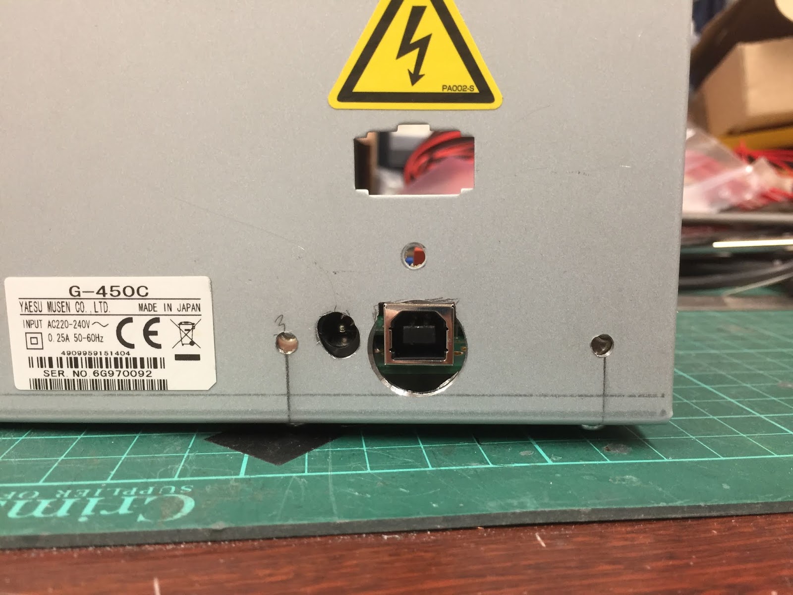
The rear of the controller box with the holes cut for the DC power
and USB connector.

Now you can see from the above picture the holes didn't quite align horizontally and this was down to me being a wally and instead of adding a couple of millimetres to the template I did the opposite and removed a couple of millimetres instead, so had I carried out that operation successfully everything would have aligned.   I still ended up with yet another problem shown below.

ERC fitted within the original rotator controller.

If you look at where the PCB stand offs are in relationship to the case fixing holes in the chassis even though there is enough height clearance so that the screws do not foul on the underside of the PCB what I hadn't taken into account was the fact the case wraps around the chassis when screwed together, this meant I needed to mount the PCB using only the two PCB mounts towards the middle of the chassis.   Now this is in fact fine the board isn't being put under any stress though these mistakes are annoying no one will be able to see them.

The original rotator gubbins replaced and the ERC cables attached.

I then replaced the front panel, power supply and original controller board with this done I could strip some insulation off halfway along both the brown and white wires this is so the ERC can be placed in parallel to the rotator and Yaesu controller to measure the feedback voltage which keeps track of the beam heading.


The control button side of the controller. 

Now the tricky part is to connect the blue and black wires from the ERC controller on the original controller heading controls these switches already have a couple of quite thick gauge wires attached to them and attaching the new wires along with the originals is a bit of a pig but if you start with the switch nearest to the mains transformer it's not too bad.

With the ERC controller connected you can refit the outer case and reconnect the unit the rotator and plug the controller back into the mains and station DC power supply you can then move on to calibrating the unit.

On the software CD you'll find two pieces of software one to calibrate the unit and another to control the unit with.  

The calibration is a little bit more involved for the Yaesu G450C rotator in that you need to do an extended calibration.   This involves calibrating at more headings than would be normal.   The general gist of the procedure is to start the calibration software as shown below.

Calibration Software
Once you have set the controllers com port, which you find in the Windows device manager, you'll be able to read the ERC memory.   Next you need to set the rotator fully counter clockwise, using the Yaesu controller, once set to 0 degrees you can perform an extended calibration by using the "Extended 1" function which measures the rotator feedback voltage at 30 degrees intervals once each interval has been measured the software will tell you to advance to the next calibration point.  

A point to be aware of is make sure when you are setting the Yaesu controller that you look straight on to the Yaesu controller heading indicator otherwise you can calibrate to the wrong heading.  

Once the calibration has been completed close the calibration software and start the rotator control software shown below.

The control software supplied with the kit.
Once the rotator control software has started remember to set the com port and wait few moments for the software to connect.   Now click on a point on the compass and the rotator should start to turn to the position you selected and check the Yaesu controller agrees with the software, try this a few times to confirm the calibration if the calibration is off you'll need to repeat the calibration again.

Though the supplied software is ok it's very basic and in fact I replaced with PstRotator from YO3DMU it's an excellent piece of software and though you need to pay 20 Euro's for the licence it's a bargain and I wouldn't use anything else.  The software can set with presets for quick heading changes, you can open a map and click at any point and the beam moves to that head, the other nice feature if you live near the coast is have the beams turn into the wind when the wind speed exceeds a threshold of you choice.

PstRotator

This is one of those projects that starts off as a 'nice to have' which turns into 'how did I ever manage without it' I'm sure no one would regret adding the ERC to their rotator controller.


Tuesday, 18 September 2018

DCI-145-2H 2m Filter.

I recently swapped an unwanted Daiwa VSWR meter for a DCI-145-2H 4 pole bandpass filter for 2 metres.   I don't really need it however I have on the odd occasion thought it might help with some strong out of band signals that occasionally pop up so swapping an unwanted piece of equipment for a piece that might be useful I thought was a good deal.

DCI quote the following specification.

Centre Frequency : 145MHz
Band Width : 2MHz
SWR : < 1.3:1
Return Loss : >18dB

DCI measure the filter response at the following intervals.

135 MHz : -72.650 dB
140 MHz : -46.450 dB
145 MHz : -0.755   dB
150 MHz : -42.981 dB
155 MHz : -65.548 dB

Out of pure interest I thought I see what I measured the above as using the DG8SAQ VNWA.

Filter response etc measured with the VNWA.
As you can see the filter specifications for SWR, RL as described the only difference is with the filter skirt readings being slightly off but in quite good agreement with DCI which I'll assume used a slightly better VNA than the one I have. ;-)

Saturday, 2 June 2018

A blast from the past my RSGB membership certificate.

I was tidying up the shack today and came across my original RSGB membership certificate dated the 1st of July 1983 a couple of days after my 12th birthday.

At the time I was very happy to receive my RS number 84784.

If my memory is correct I had to get a recommendation from a current member to join and amateur who lived across the road from me at the time filled the form out for me.

Amazingly it only took another 33 years to obtain my foundation licence and 34 years to gain the full licence, oh well better late than never. ;-)

My RSGB membership certificate issued when I twelve.

Monday, 26 March 2018

The day I was featured member on QRZ.com


Well I got up this morning and found I was the featured member on QRZ.com

M0WGF Featured Member 26th March 2018
Now I'm not sure what to make of that other than,  one I wished I had a better photo up of the shack and two what is all this web contact book all about?  Anyway funny to have been featured member for 5 minutes. ;-))