Tuesday 24 December 2019

First two months of moon bounce operations

I finally became QRV on 2m EME on the 9th of November 2019 with my first QSO with K9MRI.

I wasn't exactly trying to have a QSO but Joseph popped up on the waterfall as was so strong I thought what the hell I'd give ago and low and behold we managed my first QSO, happy days!

My system isn't yet optimised and in fact I suffer with a lot of local QRM which is hampering activity  but I think with some modifications to the antenna system in the new year should help greatly.

A pre-amp may be worth trying but I think there's probably to much noise here to able to use one but only time will see.

Anyway here's my first dozen EME QSO's.

Date Time Time Callsign Locator Distance
------ ------ ------ ------ ------
09/11/19 23:13 K9MRI EN70IU 6352km
17/11/19 00:17 UA3PTW KO93BS 2506km
07/12/19 16:17 RX1AS KO59XW 2143km
08/12/19 16:49 I2FAK JN45OB 943km
08/12/19 19:27 UR3EE KN88DC 2552km
11/12/19 19:32 HB9Q JN47CG 709km
11/12/19 19:49 S52LM JN65TX 1119km
14/12/19 21:05 I3MEK JN55SJ 1038km
14/12/19 21:15 RK3FG KO86HP 2380km

Tuesday 17 December 2019

Dual Transverter IF switch and Sequencers for Elecraft K3 / K3s


I have a medical condition called Muscular Dystrophy which results in the muscles of body slowly atrophying over time which has resulted in my hand muscles weakening to the point I struggle connecting and disconnecting any type of RF connector; this poses a problem in that I use transverters for my 2m and 70cm systems and constantly need to swap the 28MHz IF lines.

A sequencer is also employed to ensure any pre-amps are switched out of the TX signal path as well as to ensure hot switching doesn’t occur to any relays when RF is generated by the exciter.

My original setup used a single sequencer shared between transverters and other devices and though this was perfectly adequate I wanted the new system to have separate sequences where each event could be configured or modified at a later date without too much hassle.


Original Setup


Both of the transverters were built with a single RF port with an internal relay however this isn’t ideal and so I decided to modify both my transverters to provide a separate RX and TX RF ports.

My station also utilises a Wavenode RF power meter to monitor in real-time the VSWR of each antenna.  In the event of a high VSWR the Wavenode closes an internal relay this can be used to connect to an external monitor to cease operation of the station.

I recently purchased an Elecraft K3S (K3) which provides both RX and TX IF ports with the TX port output at 0dBm giving the correct level of drive for the transverters.

While reading the K3 manual I discovered the ACC port provides four TTL level logic gates where a combination of the four indicates which band is currently selected.

So with the above in mind, I decided to completely re-engineer the station to give the best receive and transmit performance I could get on the 2m and 70cm bands, reduce the amount of cable swapping and have separate sequencers for each of the transverters

The ACC port can provide PTT and TX inhibit functions which again would also reduce the amount of cabling required.

The ACC port consists of a DE-15 socket where pins 3, 9, 13 and 14 provide access to the TTL logic gates and pins 7 and 10 provide the TX inhibit (TXINHIB), which can be configured to inhibit the exciter on either a high or low state and KEYOUT-LP (PTT) which provides a 10mA sink to ground.

This was exactly what I needed to create a single control unit to switch IF lines, provide an independent sequencer to each transverter chain and to ensure that no RF was generated until all events in each sequence was completed all at the press of the band selector button on the K3 after some thought I came up with the following station configuration.


New Setup


The K3s band logic gates can be configured in one of three ways NOR for HF bands only, TRN for transverters only and HF-TRN for both the HF bands and transverters. I selected the TRN setting which made reading the TTL logic simpler as it only requires knowing the current state of two of the logic gates instead of the four gates required for the NOR or HF-TRN configurations.

From here on forward when I reference bands it is taken to also include the transverters.

The band switch logic matrix for the K3 is shown below.

K3 band switch matrix


As you can see from the table when TRN1 or TRN2 is selected the logic can either be on or off for either band but they can neither be off or on together for band 0 and 1 so any other state would be equal to another band.

So with the above in mind, I needed firstly someway to read the K3 TTL logic.

Secondly, to key the 2m and 70cm transverters as well as associated amplifiers a 10mA sink to ground is needed.

Thirdly the change over relays, Tohtsu CZX-3500, which require 12V and draw around 250mA, which would be held closed for RX operation and released for TX. The CZX-3500’s also have an advantage or providing an extra 20dB of isolation between ports compared to the ones in the transverters which only provided 40dB of isolation.

Fourthly the ability to control two mini relays to switch the IF lines between transverters.

It would also be useful to have some indication of which band has been selected as a separate confirmation to the K3, and that events for that band are being sequenced correctly.

And finally, it would be nice to have some kind of audible alert in the event of a high VSWR.

I came to the conclusion using an Arduino microcontroller would be the easiest route to getting something working fairly quickly with little expense as well as keeping the electronics side of things simple.

The Arduino UNO uses an ATMega328P which has 23 general-purpose digital I/O pins available however two are used for serial coms and one for a reset button, two pins are used for an external 16MHz crystal reference, so minus those five I/O pins eighteen pins are available to for other purposes.

I decided I need the following pins:

2 pins to read the band switch TTL logic from the K3.
3 pins to light LED’s to indicate which band has been selected on the unit.
2 pins for the IF relays.
1 pin to monitor PTT enabled from the K3.
1 pin for a PTT LED indicator.
1 pin to enable and disable TX Inhibit function on the K3.
1 pin to monitor the VSWR trip alert from the Wavenode RF power meter.
1 pin for the VSWR trip enabled warning buzzer.
1 pin for a VSWR trip reset button, for which I’ll use the default Arduino reset pin.
6 pins for the two sets of three for the sequencer, one set for each band selected.

Programming the Arduino is fairly straight forwarding using the Arduino IDE from the Arduino website. The language used is a subset of the C/C++ language which is fairly simple to use and there are plenty of resources on the internet to get you started.

The first iteration of the software was a simple loop that read the state of the I/O pins that monitor the band logic gates on the K3 and lit an LED to indicate which transverter / band was selected.

What became apparent with this first simple loop was despite the fact there aren’t any mechanical switches the software was experiencing contact bounce.

Contact bounce is caused when a switch is pressed or released and for a few milliseconds or more the switch state is unstable to get around this problem it is normal to get the state of the I/O pin and store it in variable and then wait for a defined period and check again when the stored state and current state are equal we can be sure the switch is either high or low.

There were two issues caused by the contact bounce, one if the Arduino was switched on before the K3 then the band selected on the Arduino may not agree with the band selected on the K3 and secondly, when the band was changed on the K3 occasionally the wrong band was detected.

To resolve for these issues I started writing a routine to take into account the unstable state of the switch while bouncing but in a sudden moment of genius decided not to reinvent the wheel and instead download and installed a library called Bounce2.h which reduced the amount of code I had to write for myself.

With the contact bounce cured it took an evening to write the software and that included having to remind myself how hardware is referenced on the Arduino, the web is great for these kinds of projects there’s always plenty of example code around if you’re unsure how to do something.

With the software written the next thing to do was get on with the hardware, now electronics isn’t my forte so this wasn’t something I was looking forward too.

I knew for sequence events two and three some simple NPN transistors in low side configuration would suffice however for event one I needed the ability to switch between 5V to 48V drawing up to 1A so that in the event I need to replace the change over relays I wouldn’t be restricted in what hardware could be used, so I chose to use a P-Channel MOSFET in a high side configuration.

Switch Configurations


I had a discussion with a friend who convinced me that isolating the high voltage side of the circuit would be prudent, it’s not something I would have bothered with however optoisolators are cheap as chips so I decided to isolate all of the sequencer events this would allow me to change the hardware configuration at a later date if I wanted to.

 As I had moved to the optoisolators I decided instead of turning the sequencer event indicator LED’s on direct from the ATMega I/O pins I would instead add an NPN switch in parallel to the optoisolators to sink the LED cathodes to ground instead.

This seems to be overkill but as MMBT3904 NPN transistors are only five pence each including them wasn’t going to cost any significant amount and ensure if I altered the circuit, later on, I wouldn’t run foul of exceeding the 20mA limit on the ATMega I/O pins.


Opto-isolated Switch


The complete circuit diagram is as follows.

The complete schematic


With a general plan of action, I decided instead of building the unit on stripboard I would instead have a go at using KiCad, to develop both the main PCB and front panel LED PCB.


Main board

Front panel


 I decided to place all the LED indicators, high VSWR buzzer and reset button on a small PCB, shown left, which could then be mounted to the front of the case this removed a lot of wiring that would have been required if I had mount everything individually. I used IDC connectors to connect the two boards.

The KiCad project files, Gerber files and software can be downloaded from GitHub.

I do have a couple of sets of boards spare if anyone wants to build one of these units please drop me an email, see QRZ.com, if interested.

Once the PCB’s had arrived and populated I mounted them in a Hammond ‘1550’ 275 x 175 x 67mm die-cast enclosure which matched the transverters.

Font Panel

Rear Panel

Interior

Monday 16 December 2019

70cm 250W Amplifier from secondhand DVB-T PA Part Three

You may remember in my first blog post about this amplifier I mentioned I had bought from eBay an LPF for the unit and I was a little worried this wouldn't perform as well as the eBay listing had lead me to believe.

I've finally managed to get hold of a cheap HP 8594e spectrum analyser from a fellow amateur through the second-hand advertisements in the back of RadCom and the seller very kindly included a nice directional coupler in with it, so with spectrum analyser and coupler in hand, I decided after much reading to finally connect it all up with the amplifier and see what the output looked like.

70cm Amplifier Output at 140W
You can see from the above any harmonics that are present are at least -60dBc.   The test was performed using the two tone generator within the Elecraft K3s.

Monday 9 December 2019

70cm 250W Amplifier from secondhand DVB-T PA Part Two

With the amplifier built the next item on the list was finding a power supply for it.   Originally I was going to use two HP DPS-600PB server supplies in series which would have given around 28V at 55A.

While building the amplifier I had an email from a fellow amateur Steve G4MJW asking what LPF I was using and we have been helping one another out with ideas since.

One of Steve suggestions was to use an old Ericsson 27.2V 55A PSU from a RBS 2216 900MHz GSM station which are / were available on eBay for £28 plus postage.    The nice thing with the Ericsson PSU over the HP server modules was the fact everything was in one unit.  

I couldn't find much information on these PSU however I did find a German website detailing a tear down of the RSB2216 unit including the PSU with a rather handy note that you would adjust one of the trimpots, the one on its own furthest from the three that are in line,  to increase the output voltage to 28.2V from the standard 27.2V.

One thing Steve noticed before me as he ran his for longer than a few minutes was the temperature of the case which was hot to the touch to the point the unit turned itself off.  

I ran mine for and hour and half an in that time the temperature got up to a rather barmy 39 degrees C, so some cooling was in order.  

My original thought was to use some small 30mm fans attached to the rear plate of the unit but in the end I went with two 28V 80mm fans purchased from eBay.  

The fans worked great and in fact I think a single fan would suffice and to be honest two or three 30mm fans on the back would also probably be enough.

With the fans installed the unit now runs cold so a success all in all.

The next thing to do was find a way of connecting equipment to the unit and again Steve came to the rescue when he pointed out he'd bought some banana jack sockets from eBay that by chance happened to have a thread big enough to self tap in the original DC power socket.

All in all modifying the PSU and getting it and running took an afternoon of drilling and filing to fit the fans and 10 minutes to wire it all up.

I have to thank Steve greatly for coming up with this PSU it saved me an awful lot of mucking around and gave a nicer / safer unit than the HP server supplies.

The finished PSU


Tuesday 26 November 2019

70cm 250W Amplifier from secondhand DVB-T PA Part One

When I last posted in June I mentioned I had bought a secondhand DVB-T PA from a German eBay seller well I've finally got around to putting it all in a box and getting it up and running.

The PA module is simple to modify and in fact I found during an internet search a website by a Dutch amateur PA0EHG who had already modified one of these amplifiers and I followed his instructions which worked perfectly.

The PA is coupled with a LPF again from eBay which looks like it's a based on a design by Jim W6PQL the specifications where 2nd order harmonics -35dB and 3rd order -55dB with an insertion loss less than 0.15dB.

When measured with the VNA I found the 3rd order harmonic weren't rejected as much as specified so I expect it might need another coaxial stub filter to drop the 3rd order harmonic a little more.

70cm eBay LPF filter response.
I put the LPF in a tin box bought from Alan G3NYK though I had to buy a bigger box than was required and trim it down to size using tin snips.

To monitor the amplifier I was going to roll my own controller board but again Jim W6PQL has what he calls the ultimate amplifier controller board which at $50 for a kit I thought was a bit of bargain and a lot less hassle than making my own even if half the features of the board aren't being used.

I stuck all this in a rather large Hammond box so its ended up not being a small amplifier but you go with what you have laying around the shack.

I painted the case in acrylic paint and though the result was good looking I don't hold out much hope for it's long term durability.

Front Panel
Reat Panel
Top View
Internals

The amp requires a quite hefty PSU 31V 17A but more on that in later post.

Saturday 9 November 2019

First EME QSO.

I've just spent a couple of days listening to the moon and getting nowhere using WSJT-X.

When I use WSJT-X with the K3s I have a hell of time trying to the get the RX levels right with the K3s LIN OUT set to 1 the PC Microphone level is set at 0.4dB the RX level indicator in WSJTX is still at 60dB and I haven't a clue why, anyway the upshot is I only had a couple of decodes.

Anyway I switched to MSHV and low and behold multi decodes within 60 minutes of using it, yippie!

So with half an hour before bed I noticed K9MRI in EN70IU and thought what the heck I'd give it ago not expecting much with such a small antenna array and low and behold we completed.

I'm now off to party it's been a hard slog getting that first QSO via EME and I'm ecstatic or should that be over the moon?

First EME contact with K9MRI.


Friday 8 November 2019

Another change of the 2m antenna system.

Though the 2 x 9 Element Powabeams I put up last year worked well I really wished I'd installed a system that had elevation and so I've now replaced the Powabeams with a small array 4 x 6 Element LFA from Innovantennas.

Justin also provided the H frame as well as a new boom for the 70cm 12 element LFA I had so it could be rear mounted in the centre of the frame.

While I was buying the antennas I also bought a SPID RAS rotator with Rot2Prog controller but more about that in a later post.


The new array took around five days to put but mainly down to the fact I hadn't ever installed this type of system and so it took a lot longer than it would if I was to get it all done again.   The main time consumer is in the fact I don't have a tilt over mast and so everything has to put up with the aid of an Aluminium tower.   

The array tuned up quite well with each beam within a half a dB of RL.

Top Left      Z 50.6, X 3.7, SWR 1.07, RL 28.6
Top Right     Z 52.6, X 3.2, SWR 1.08, RL 28.1
Bottom Left   Z 53.0, X 2.8, SWR 1.08, RL 28.1
Bottom Right  Z 51.9, X 3.6, SWR 1.08, RL 28.2 

The whole array including coupler and 16m of Ultraflex 10 gave an SWR of 1.1:1

Justin kindly send me a theoretical  plot of the array at 8m high with a spacing of 2.2m horizontal and 2m vertical separation.


Theoretical Azimuth Plot.
You can see from the plot the gain is quoted as 17.36dBi with a F/B of 23dB and beamwidth of 24 degrees.  

I took my own plot using the GB3VHF beacon which is near to me and was about to plot the results out by hand when I did a search for a blank azimuth polar plot and instead came across a great piece of software by Bob Freeth G4HFQ called PolarPlot  this small piece of software saved me a good amount of plotting everything myself and I highly recommended it.

I measured the gain as being 18.48dBi with a F/B of 22dB and a beamwidth of 24 degrees so in good agreement with Justins theoretical calculations.

Azimuth plot as actually seen.

The rear lobe are a bit weird but then there isn't much space between the antennas and surrounding builds, hills, slopes, overhead wires but even so it looks very good.

Friday 14 June 2019

Just a quick update to say I'm still kicking.

Been a quiet month or so and so I thought I better write something for this blog.  ;-)

First off I got fed up trying to get a clean signal from the Gemini 2-500 PA using the Anglian transverter and Icom 7300.   No matter what I seemed to do I could not stop it from occasionally causing splatter, along with the RF surges in power when first keying the transmitter.    Now this isn't to say the IC7300 is a bad radio it isn't but it certainly doesn't like playing the transverter and Gemini.    So to resolve the issue I went and bought an Elecraft K3S which has resolved all the issues and ok it's an expensive fix but the transmitter of the K3S is certainly worlds ahead of the IC7300, though I do still prefer the audio from the 7300 which is much easier on the ears.  

One of the nice things about using the K3S is the fact it displays the right frequency when using the transverters and in fact with in a few days of having it I also discovered it out from TTL logic from the ACC port so you can interface some kind of transverter switching.    

With the above in mind I wondered if a simple transverter switch and device sequencer could be bought and though I did find a couple they were quiet expensive so I decided to roll my own using an Arduino so a couple of prototypes later I've come up with a design with will switch between my 2m and 70cm transverters and handle the device sequencing for both units below is a couple of screenshots from KiCad of the front panel indicator and main board.  I'll do a full write up once I've confirmed all works as expected.  

A quick feature list is as follows.


  1. Handles two transverter. 
  2. Provides TX inhibit. 
  3. First sequence event can provide 12 - 28V up to a couple of amps to drive change over relays.
  4. Sequence events two and three can sink up to 40mA, though you could chuck in a darlington pair if you want to sequence more relays.
  5. The unit interfaces with my Wavenode so that if a high VSWR is seen the unit automatically ceases transmitting and puts the unit into the default RX mode.
  6. All sequence event are optocoupled to the Arduino just in case a FET or BJT decides to go legs up in a funny way.
Front panel layout from KiCad
Main board layout from KiCad.

I've also got another project on the go in the form of a 70cm 250W amplifier which I bought from eBay from a German amateur which was quite cheap at 55 Euros.  

70cm 250W PA module from eBay.
I rather helpfully came across the website of PA0EHG who had bought the same unit and documented what he had done to get the unit going on the 70cm band so once I've got a replacement RF terminator as the one that came with the unit the solder tab fell off as soon as I touched it I'll power it and see what's what.

So that's the end of this update I'll do a proper update once everything has progressed a bit further.


Wednesday 3 April 2019

The Y Factor

Over the past couple of years I’ve been attempting to build a high performance two metre station and as such have been slowly making modifications and upgrades with that goal in mind. One of the upgrades I carried out was to change from an FT991 to an IC7300 coupled with an Anglian 3L two meter transverter from G4DDK1.

Though the upgrades and modifications have worked quite well I felt there was still room for improvement but with no quantitative measurements being taken during the upgrades you start to fool yourself with how those changes are actually performing.

A good indication of receiver performance is to measure the noise figure, the Anglian 3L has a quoted noise figure of between 1.6 - 1.8 dB whereas the FT991’s noise figure is 5 dB at two metres, so how do we go about doing measuring this for ourselves?

Caveat :  I’m not going to talk too much about what is a Y factor measurement or about noise figures in general there are two excellent documents from Keysight that explain both in far more detail than I could do justice, these two documents are called “Fundamentals of RF and Microwave Noise Figure”2 and “Noise Figure Measurement Accuracy: The Y-Factor Method”3.

So what does the noise figure represent?  Well the noise figure is a measurement of the degradation of the Signal to Noise Ratio introduced into the signal chain by the devices which make up the chain,  a lower figure indicates better performance. 

To measure the noise figure of a receiver you require two pieces of equipment a calibrated noise source and a means of taking the measurement.

A good quality calibrated noise source from Ailgent would cost you hundreds of pounds even for a second hand one which is out of reach of most amateurs.   

There is an alternative however available in the guise of the RXGen noise source from RFDesign4, also  available from the same company are the RFD2305 ENR 5dB  +/- 0.25dB and the  RFD2315 ENR 15dB +/- 0.25dB precision noise sources available for around twice the cost.

The RXGen is a 2MHz - 2.4GHz noise source with a measured ENR (Excess Noise Ratio) of 10dB +/- 0.5dB which costs seventy eight pounds including postage.    

This means you can take measurements with an accuracy of +/- 0.5dB. We will also need someway of measuring the noise figure but again a good quality noise figure meter such as the HP 8970 PANFI is likely to set you back hundreds of pounds second hand.  

We can however use simpler equipment but with the proviso we accept we’ll not be able to measure noise figures below 2dB with any certainty.

A ‘Y’ factor measurement is defined as the ratio between thermal noise, defined as 290k for a 50ohm calibrated load at an ambient temperature of 17 deg C, and  the noise source when switched on, we can make the measurement as a simple voltage ratio or the difference between the two measurements in measured in decibels.  

It’s worth mentioning temperature can have a profound affect on the measured noise figure this especially comes in to play for low noise figures.

There are a number of ways of taking the measurement the simplest being to use a digital voltmeter,  the accuracy of using this method will be dependant on the quality of the meter employed,  I used a cheap UNI-T meter and obtained good results despite the meter not being a true RMS model.  

The second method uses a PC’s sound card with either SpectraVue5 in continuum mode or an excellent piece of software called NFM from Owen Duffy VK2OMD6.

So let's try to measure the NF of a Icom 7300 on the 10m band with pre-amp one switched on.

To measure the noise figure  we first need to connect a calibrated 50ohm load to antenna socket.

The RXGen will act as a 50ohm load when unpowered, technically we should use a calibrated 50ohm load but I’ve found the difference in measured noise figure is smaller than the indicated accuracy of measurement available and as such the RXGen is a perfectly adequate.

Before taking the measurement ensure the radio’s AGC is set to off otherwise set it to its slowest available setting. 

Next we need to connect the headphone or speaker output to the DVM,  I used a 3.5mm stereo jack to a couple of banana plugs to connect the DVM via the IC7300 headphone socket.

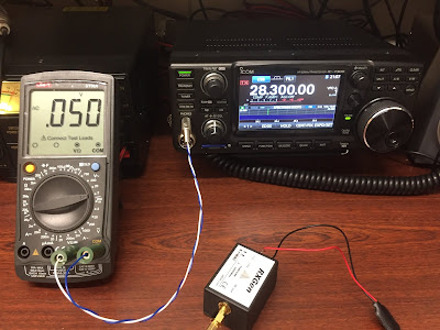
With the load connected set the radio’s audio gain for a quiescent value of say 50mV.

You can see in the following image the meter reads 50mV in reality the meter will vary by a few millivolts either way so I tend to watch the meter for a few seconds and take the lowest value.


Meter reading noise source switched off.

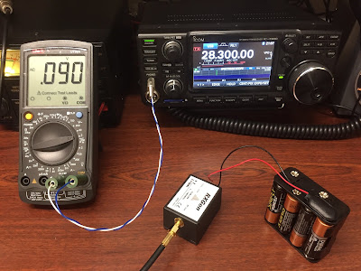
Next we apply power to the RXGen and read the lowest active value in this case 90mV.

Meter reading noise source switched on.

To find the Y factor we need to find the ratio between the quiescent and active values,  90 / 50 = 1.8, we can then use the chart supplied with the RXGen to find the noise figure for the given voltage ratio.   


Note you can calculate this by hand using the formulae given in the Keysight documents but with the level of accuracy available with the RXGen the chart method is perfectly adequate.

Measured NF using Voltage ratio method.

Reading from the above chart the measured noise figure is approximately 6.3dB,  which is near to the figure quoted by Icom for the IC7300 of 7.12dB for the 10m band with the first pre-amp switched on.

When taking measurements with a DVM I would advise you take more than one reading and take the average however I found even if you do this unless, you have a true RMS meter, the result can be off by +/- 1dB.

A more accurate way to measure the Y factor is to use SpectraVue, you will need to connect the device to be tested via either its headphone or speaker output to the computers sound card, this can lead to ground loops so it would be best to use a sound card such as the Signalink to carryout any measurement or use a 1:1  isolation transformer.  

The IC7300 has a built in sound card so I will use that to carry out the measurement,  however this will mean the noise figure of the sound card will also be included in the measurement.

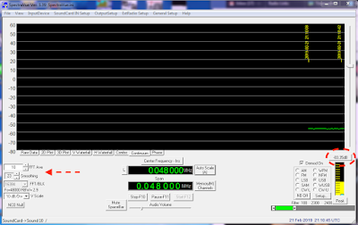
You can see in the image below SpectraVue is running in continuum mode with FTT averaging and smoothing applied, indicated by the red arrows, with the load connected SpectraVue gives a quiescent value of -83.35dB circled in red.

SpectraVue quiescent measurement.
Applying power to the  RXGen wait for the peak reading to stabilise in SpectraVue at which point obtain the active value -78.48dB, shown circled in red below.

SpectraVue active measurement.
Subtracting the quiescent value from the active value will yield a Y Factor in dB of 4.87dB.

Again using the documentation that comes with the RXGen we can read off the chart to obtain a NF reading of 7dB as shown below.
Y Factor measurement using dB method.
We can see the reading is in agreement with the published NF and very close to our original reading using the DVM method.

The last method utilises a piece of software called  NFM from Owen Duffy VK2OMD the software is restricted by default to an integration interval of 0.5s  you can however request a licence from Owen if you want to use a long interval,  you can find his email address on qrz.com he’ll email you a licence for free eventually.

When using NFM you must enter the noise source’s specified ENR specified in the case of the RXGen 10dB as depicted in the below image.

To obtain a reading set the sound card you are using as the default device for the system otherwise NFM will not use it. 

With the noise source switched off press the ‘1 Noise LO’ button indicated by the red ‘A’ once a quiescent value has been found apply power to the RXGen and press the ‘2 Noise HI’ button indicated the by the red letter ‘B’ after a moment the calculated noise figure will be displayed as circled in red.

NFM will indicate if the sound cards level is either too high or low by displaying a line of red asterisks, in this case just adjust the level to a suitable value using the gain controls for the device being used.

NFM noise figure measurement.
We can again see this is in agreement with SpectraVue if you look at the Y(2)(dB) field, shown above, it gives the Y factor in dB which is 4.88dB  a difference of 0.01dB but this time we have a slightly better noise figure of 6.83dB since this is calculated by the software and not reliant on use reading from the supplied chart. 

I have also included below an image of NFM doing the same measurement but with a longer integration interval of 30s and you see the noise figure has only changed by 0.2dB this indicates the longer integration interval isn’t of any real use when using the RXGen noise source. 


NFM extended integration time.
The nice thing about NFM is its ability to do multiple stage measurements simply and quickly without having to crunch the numbers by hand saving a quite a bit of time if you’re making a lot of measurements.

In the following example the equipment is set up in the following manner which is my default operating configuration.

NOTE : Normally you wouldn’t have any additional attenuation in the signal path when taking a two stage measurement it’s only included here because of the difficulty I have in reconfiguring my equipment.
System configuration for two stage measurement.
First take a reading with just the RXGen and IC7300 connected, as we did in the above example, first by pressing the button labeled A to take the quiescent value and then the button labeled B with the RXGen powered to take obtain the active value which yields a noise figure of 6.28dB circled in blue.

Next we add the Anglian 3L, 3dB splitter and 20dB attenuator in to the signal path.   

Now find the quiescent state value by pressing the button labeled C.

For a two stage measurement you must include any attenuation between devices otherwise the measurement will either not work or be inaccurate, so we enter the total value of any attenuation in the box labeled D.

Lastly we find the active state value by powering on the RXgen again and pressing the button labeled E this yields a total noise figure for the system of 6.48dB again circled in blue.

You may ask yourself why is the noise figure so high if the Anglian has a stated noise figure of 1.9dB?  The reason for this is the attenuation introduced by the splitter and attenuator negates any additional gain the Anglian has provided and therefore resulting in a noise figure is more or less in line with the specified noise figure for the IC7300.

However since we’ve done a two stage measurement we can find the noise figure and RX gain of the Anglian by looking at the device under test section of NFM where we can see we have an RX gain of 25dB and a noise figure of 2.5dB both circled in red.  

This is in good agreement with the Anglian’s quoted specification of an RX gain of 25dB and noise figure of 1.9dB. 

NFM two stage measurement.
It’s worth pointing out the additional passive devices and cables in the signal path will have affected our measured noise figure for the Anglian you should attempt to keep any cabling between devices as short as possible at lower frequencies even the leads from the battery can add additional noise.

I hope this short article has encouraged you start experimenting with taking noise figure measurements with a simple low cost noise source it can lead to hours of fun discovering where or where not your system is performing as expected. 

  1. http://www.g4ddk.com
  2. http://literature.cdn.keysight.com/litweb/pdf/5952-8255E.pdf
  3. http://literature.cdn.keysight.com/litweb/pdf/5952-3706E.pdf
  4. http://g8fek.com/noise-gen.html
  5. http://www.moetronix.com/spectravue.htm
  6. https://owenduffy.net/software/nfm/index.htm
This article was first published in the March 2019 edition of QUA the new letter of the  Cray Valley Radio Society.

Wednesday 27 March 2019

A Tale of Spectrum Pollution - Update 2

Typically as soon as a couple of kind amateurs from my radio club arrange to come down and to DF the source of the noise on 2m and 70cm which has been present for 9 months switching on and off at the same time it packs up, grrrrr.  

The noise has dropped from S6 between 15:00 - 08:00 to S4 between 08:00 - 22:00 by the looks of it the best we might be able to reduce the noise to is S3 but and improvement of 18dBm.

Original spectrum pollution measurement.

Latest spectrum pollution measurement.


Monday 11 March 2019

A Tale of Spectrum Pollution - Update

My original measurements of spectrum pollution at JO01JK were slightly off.   It turned out the noise floor for the sound card in SpectrumLab was -97dBFS and as such when I took the first measurement with the 50ohm calibrated load connected the generated noise was below the noise floor of the sound card, I've now corrected for this and taken another measurement.

Noise against HF calibrated S-Meter

Noise against VHF calibrated S-Meter

This seems to show the noise here isn't quite as bad as I originally thought though the 6dB rise in noise caused by the apparent outside light coming on is still annoying and will need to be tracked down and fingers crossed replaced.

All the measurements I've taken so far are to the West which is the worse direction for noise and so I'll need to repeat the measurements every 45deg from North at some point just to get a base level at which to compare any apparent increase in noise in the future.

While I was at it I also did a quick calibration of the S-Meter on the IC7300 with the Anglian 3L 2m transverter using a Marconi TF2015 signal generator.   I set the output of the TF2015 to -47dBm I then used some SMA attenuators to reduce the level down to the various S-Point values for a HF receiver so in some cases I'm up to 2dB off the required power.

All measurements taken in 2.7kHz bandwidth with the AGC set too slow.

Saturday 9 March 2019

A Tail of Spectrum Pollution.

Last autumn I installed a new antenna system for two metres and immediately notice a huge rise in wideband noise and birdies across the whole two metre band, other bother!

As with all these things I tend to go at it like a bull in a china shop and only afterwards realise I should have taken some measurements of noise or even of the local beacon, oh bother!

Well the first thing to do is turn the mains power off to house and take a quick look a the waterfall on the rig compared with it on.

Mains switched off.

And with the mains switched back on again.

Mains switched on.

Wow! Ok I wasn't expecting that.  

Next thing to do is turn the mains off again and slow turn each circuit back on by the fuse box, in my case everything stayed looking good until I hit the sockets that power all my AV equipment and WIFI / Lan access point at which point all the birdies flew back in. ;-)

Next up I switched off all the AV equipment and the router and slowly switched each item back on the first item happened to be the access point and low and behold the waterfall filled up again.

I then unplugged everything from the access point other than the power supply and again the interference vanished so wasn't being caused by the WIFI, SMPS or the unit itself.  

Now I should mention I run CAT5 cabling to various devices such as the media server, sky box etc ... 

For each CAT5 cable I wound 6 turns around a type 43 ferrite torrid, available from the RSGB shop,  at both ends of each CAT5 cable in turn checking each time if the birdies had reduced.   

What I found was any cable run over half a metre in length need to have ferrites fitted and with the longer run cables, in excess of  a metre, need two of more ferrites at each end to get enough impedance to reduce the birdies. 

After what seemed like an extraordinary length of time, hey these things take ages to do from a wheelchair, I finally managed to get a handle on the birdies to the point they're almost no existent. 

Noise after ferrites fitted.

Ok this is looking good a lot better than it did originally, and again being a wally I should have a taken a measurement of the overall noise floor and not just glance at the waterfall.

So I next setup SpectrumLab to log my local noise pollution towards the West for a few days to measure the general noise level. 

SpectrumLab with Plotter logging Spectrum Noise.

To calibrate the system I took a long plot to start with of a calibrated 50ohm load @ 290K with a 2.7kHz bandwidth.

A 50ohm load at 290K is equal to -174dBm/Hz so in a 2.7kHz bandwidth -140dBm.

I only I had a couple of days measurement I wrote a quick Python program to display the results in dBm's and S-Points.  
   
Now S-Points, a totally bloody useless measurement of anything if you ask me. ;-)  I had a quick look at S-Meters on Wikipedia and there appears to be two IARU technical recommendations for S-Meters one for HF defined as -73dBm for S9 with a 50 ohm impedance and another for VHF as being -93dBm for S9 again with a 50ohm impedance system  both with 6dB increments between points. 

So I did two plots one with the HF specification 

Scaled with HF S-Meter Specification.

and another with the VHF spec.

Scaled with VHF S-Meter Specification.

The first thing we can see if the chart using the VHF S-Meter specification looks horrendous while the HF doesn't look that bad and I'm inclined to go with the HF chart instead.

The second thing we can notice is at around 15:00 everyday and until 08:00 the following morning there appears to be an outside light being switched on which is raising the noise floor by 6dB so that'll  need to be tracked and sorted out.   

I still need to take some measurement with the house mains off again just to see if the noise floor drop at all but I do now feel as if I getting a handle on situation even if there's plenty left to do. 
  

Friday 1 March 2019

Kuhne Electronics IC7300 IF Transverter Mod Board - Update 2

I original posted I had issues with the Kuhne IC7300 IF interface and had removed the modification, I now believe the issue was partially the interface and board and partially a user issue.

I bought a new interface board and fitted it along with the additional 47ohm resistor that is meant to resolve the TX oscillation issues and so far no funnies have been seen.

The issues I originally reported with the RX side of things were all due to my lack of understanding than to do the interface board.  

The main issue was the Anglian 3L transverter gives about 21dB gain this is such a high amount of gain it reduced the dynamic range considerably which though it made the receiver very hot it also picked up all the local RF noise was causing me a headache.

What I've since realised is I should have added some attenuation to the RX path before the 7300 in fact I've added just enough to give me a noise figure or around 2dB which is in line with the quoted specification for the Anglian this results in almost no loss in dynamic range.

The only problem I found was having such a hot receiver was I need to pay a lot more attention to local generated RF noise than I had previously and after an afternoon of slowly switching all the electronics off the house and a huge amount of ferrite I managed to reduce the noise and birdies by 10dB.

So I need to apologise to Kuhne for writing such a horrid review of the IC7300 IF interface when the reality is most of the issues were down to me being a draft bugger.