Wednesday, 27 March 2019

A Tale of Spectrum Pollution - Update 2

Typically as soon as a couple of kind amateurs from my radio club arrange to come down and to DF the source of the noise on 2m and 70cm which has been present for 9 months switching on and off at the same time it packs up, grrrrr.  

The noise has dropped from S6 between 15:00 - 08:00 to S4 between 08:00 - 22:00 by the looks of it the best we might be able to reduce the noise to is S3 but and improvement of 18dBm.

Original spectrum pollution measurement.

Latest spectrum pollution measurement.


Monday, 11 March 2019

A Tale of Spectrum Pollution - Update

My original measurements of spectrum pollution at JO01JK were slightly off.   It turned out the noise floor for the sound card in SpectrumLab was -97dBFS and as such when I took the first measurement with the 50ohm calibrated load connected the generated noise was below the noise floor of the sound card, I've now corrected for this and taken another measurement.

Noise against HF calibrated S-Meter

Noise against VHF calibrated S-Meter

This seems to show the noise here isn't quite as bad as I originally thought though the 6dB rise in noise caused by the apparent outside light coming on is still annoying and will need to be tracked down and fingers crossed replaced.

All the measurements I've taken so far are to the West which is the worse direction for noise and so I'll need to repeat the measurements every 45deg from North at some point just to get a base level at which to compare any apparent increase in noise in the future.

While I was at it I also did a quick calibration of the S-Meter on the IC7300 with the Anglian 3L 2m transverter using a Marconi TF2015 signal generator.   I set the output of the TF2015 to -47dBm I then used some SMA attenuators to reduce the level down to the various S-Point values for a HF receiver so in some cases I'm up to 2dB off the required power.

All measurements taken in 2.7kHz bandwidth with the AGC set too slow.

Saturday, 9 March 2019

A Tail of Spectrum Pollution.

Last autumn I installed a new antenna system for two metres and immediately notice a huge rise in wideband noise and birdies across the whole two metre band, other bother!

As with all these things I tend to go at it like a bull in a china shop and only afterwards realise I should have taken some measurements of noise or even of the local beacon, oh bother!

Well the first thing to do is turn the mains power off to house and take a quick look a the waterfall on the rig compared with it on.

Mains switched off.

And with the mains switched back on again.

Mains switched on.

Wow! Ok I wasn't expecting that.  

Next thing to do is turn the mains off again and slow turn each circuit back on by the fuse box, in my case everything stayed looking good until I hit the sockets that power all my AV equipment and WIFI / Lan access point at which point all the birdies flew back in. ;-)

Next up I switched off all the AV equipment and the router and slowly switched each item back on the first item happened to be the access point and low and behold the waterfall filled up again.

I then unplugged everything from the access point other than the power supply and again the interference vanished so wasn't being caused by the WIFI, SMPS or the unit itself.  

Now I should mention I run CAT5 cabling to various devices such as the media server, sky box etc ... 

For each CAT5 cable I wound 6 turns around a type 43 ferrite torrid, available from the RSGB shop,  at both ends of each CAT5 cable in turn checking each time if the birdies had reduced.   

What I found was any cable run over half a metre in length need to have ferrites fitted and with the longer run cables, in excess of  a metre, need two of more ferrites at each end to get enough impedance to reduce the birdies. 

After what seemed like an extraordinary length of time, hey these things take ages to do from a wheelchair, I finally managed to get a handle on the birdies to the point they're almost no existent. 

Noise after ferrites fitted.

Ok this is looking good a lot better than it did originally, and again being a wally I should have a taken a measurement of the overall noise floor and not just glance at the waterfall.

So I next setup SpectrumLab to log my local noise pollution towards the West for a few days to measure the general noise level. 

SpectrumLab with Plotter logging Spectrum Noise.

To calibrate the system I took a long plot to start with of a calibrated 50ohm load @ 290K with a 2.7kHz bandwidth.

A 50ohm load at 290K is equal to -174dBm/Hz so in a 2.7kHz bandwidth -140dBm.

I only I had a couple of days measurement I wrote a quick Python program to display the results in dBm's and S-Points.  
   
Now S-Points, a totally bloody useless measurement of anything if you ask me. ;-)  I had a quick look at S-Meters on Wikipedia and there appears to be two IARU technical recommendations for S-Meters one for HF defined as -73dBm for S9 with a 50 ohm impedance and another for VHF as being -93dBm for S9 again with a 50ohm impedance system  both with 6dB increments between points. 

So I did two plots one with the HF specification 

Scaled with HF S-Meter Specification.

and another with the VHF spec.

Scaled with VHF S-Meter Specification.

The first thing we can see if the chart using the VHF S-Meter specification looks horrendous while the HF doesn't look that bad and I'm inclined to go with the HF chart instead.

The second thing we can notice is at around 15:00 everyday and until 08:00 the following morning there appears to be an outside light being switched on which is raising the noise floor by 6dB so that'll  need to be tracked and sorted out.   

I still need to take some measurement with the house mains off again just to see if the noise floor drop at all but I do now feel as if I getting a handle on situation even if there's plenty left to do. 
  

Friday, 1 March 2019

Kuhne Electronics IC7300 IF Transverter Mod Board - Update 2

I original posted I had issues with the Kuhne IC7300 IF interface and had removed the modification, I now believe the issue was partially the interface and board and partially a user issue.

I bought a new interface board and fitted it along with the additional 47ohm resistor that is meant to resolve the TX oscillation issues and so far no funnies have been seen.

The issues I originally reported with the RX side of things were all due to my lack of understanding than to do the interface board.  

The main issue was the Anglian 3L transverter gives about 21dB gain this is such a high amount of gain it reduced the dynamic range considerably which though it made the receiver very hot it also picked up all the local RF noise was causing me a headache.

What I've since realised is I should have added some attenuation to the RX path before the 7300 in fact I've added just enough to give me a noise figure or around 2dB which is in line with the quoted specification for the Anglian this results in almost no loss in dynamic range.

The only problem I found was having such a hot receiver was I need to pay a lot more attention to local generated RF noise than I had previously and after an afternoon of slowly switching all the electronics off the house and a huge amount of ferrite I managed to reduce the noise and birdies by 10dB.

So I need to apologise to Kuhne for writing such a horrid review of the IC7300 IF interface when the reality is most of the issues were down to me being a draft bugger.

Tuesday, 1 January 2019

Squares, squares, squares 2018

Well the new year has been and gone and as we head into 2019 I thought it would be interesting to see my stations performance on 2m and 70cm since I was first licenced.  

The station setup has evolved greatly on the past 12 months and so I thought I'd share the evolution and how it performed.

In 2017 I started the year with a Yaesu FT991 with a single 9 element 2m LFA  and 13 element 70cm LFA from G0KSC, my maximum output power was 50W.

2m Squares 2017

You can see from the above I managed to work 55 squares using mainly SSB, JT65, FSK and JTMS.


70cm Squares 2017

Again from the above we see I managed a rather pathetic 9 squares all on sideband.  

In 2018 the station evolved from the FT991 to using homebrew transverters the rather fine 2m Anglian 3L and 70cm Iceni units from G4DDK.  I swapped to an Icom IC7300 for the exciter. 

The 2m system started the year with a Microset SR100 100W linear and ended the year with the mighty fine Gemini 2-500 500W linear from the dxshop.    

I actually had the amplifier and running before I got around to updating the 2m antenna system not because this is the right way but down to the fact taking an amplifier out of the packaging is a lot easier than updating the antennas. 

I then changed the 2m antenna system from the single 9 element KSC to a stack of 2 x 9 element G4CQM's from Powabeam.   

It took me awhile to get the new CQM's built as I bought them as kits from Powabeam which meant I need to cut the elements and construct the driven element.   I got the new system up and running at the beginning of September and it worked like a dream right up until it rained hard when the VSWR suddenly went to infinity so that put paid to any 2m work for September. 


2m Squares worked from JO01 2018

You can see from above a slight improvement in performance this year and I think I managed to miss just about every opening typical!  Anyway I still managed to work 86 squares and good improvement over the 56 from the year before.

The 70cm system didn't change much beyond the move the to the Iceni I stayed with the same antenna setup as the previous year still driven with 50W.

70cm Squares worked from JO01 2018

You can see I didn't work on 70cm too much mainly down to no easy way of switching between the transverters but I still managed to work 25 squares, mostly during the 70cm UKAC, but still a big improvement on the 9 squares the previous year.  

Fingers crossed 2019 will be even better and I'm actually near the shack during any opening but we'll have to wait and see.

Wednesday, 12 December 2018

Easy Rotator Control 4 and the Yaesu G450C Rotator.

For ages now I've been reaching across the bench keeping my finger pressed on the rotator controller switch when changing beam heading and I've finally got fed up with the agro of doing this when a PC based solution is available in the form of the Easy Rotator Controller (ERC) from schmidt-alba.

The ERC is small PCB consisting of relays and a ATmega micro controller to monitor the rotator feedback voltage and operate the relays taking on the role of the existing CW and CCW switches.

The controller is available in a number of configurations, I choose to purchase the Version 4 USB controller as most PC's today do not come with a built in serial port.

The controller is available as either a kit or prebuilt.   I  decided to get the kit form, as any respecting amateur would, for £79.47 including postage and packing which is a £20 pound saving on the prebuilt unit.

The kit comes in four packages consisting of a high quality USB cable, software CD, component bag and another bag with the PCB, DC power connector and some cable to wire the ERC up to your existing controller.

Contents of ERC kit package.

The component bag consists of all the components to be soldered onto the supplied PCB.

The supplied kit components.
PCB, DC power plug, cable and PCB standoffs.

The kit has very few parts as you would expect based around a ATMega 328P 8 Bit micro controller, a crystal for the processor clock some capacitors, a couple of diodes and chokes, a few resistors and a small 70cm x 60cm PCB plus the USB interface, relays and terminal blocks.

I started by first installing all the discrete components, IC holders and the USB interface board which took about half an hour to complete.

The completed board minus relays and terminals.

Once the above was completed I installed the rest of the components.

The completed board ready for the IC's to be fitted.

Once the board is completed you apply 12V DC to the unit and test that you get 12V and 5V at the test points located on the DC port side of the board assuming these pan out you insert the ICs and then start modifying the original rotator controller to take the ERC board.

With the easy bit completed the next job is to disassemble the Yaesu controller and do some metalworking.

Taking the Yaesu controller unit apart isn't a five minute job what you need to do is unplug the power cable from the front power switch and then pop out the cable clamp and remove the lead from the case, you next need to desolder the fuse holder from the transformer and remove holder from the chassis again this isn't easy as everything is covered in blue thread lock, next up remove the control cable 6 pin molex socket.    With all the cables removed you now need to remove screws holding the top instrumentation tray to the front and back panels, this is done to allow access to the nuts and bolts holding the mains transformer to the bottom of the chassis which again has blue lock thread, Yaesu really don't want this unit to fall apart. ;-)   With all the above removed you can now get on with marking the holes from the DC PWR and USB ports.

There's a handy sticky label template that comes with the ERC controller which is perfect for marking the hole placements.

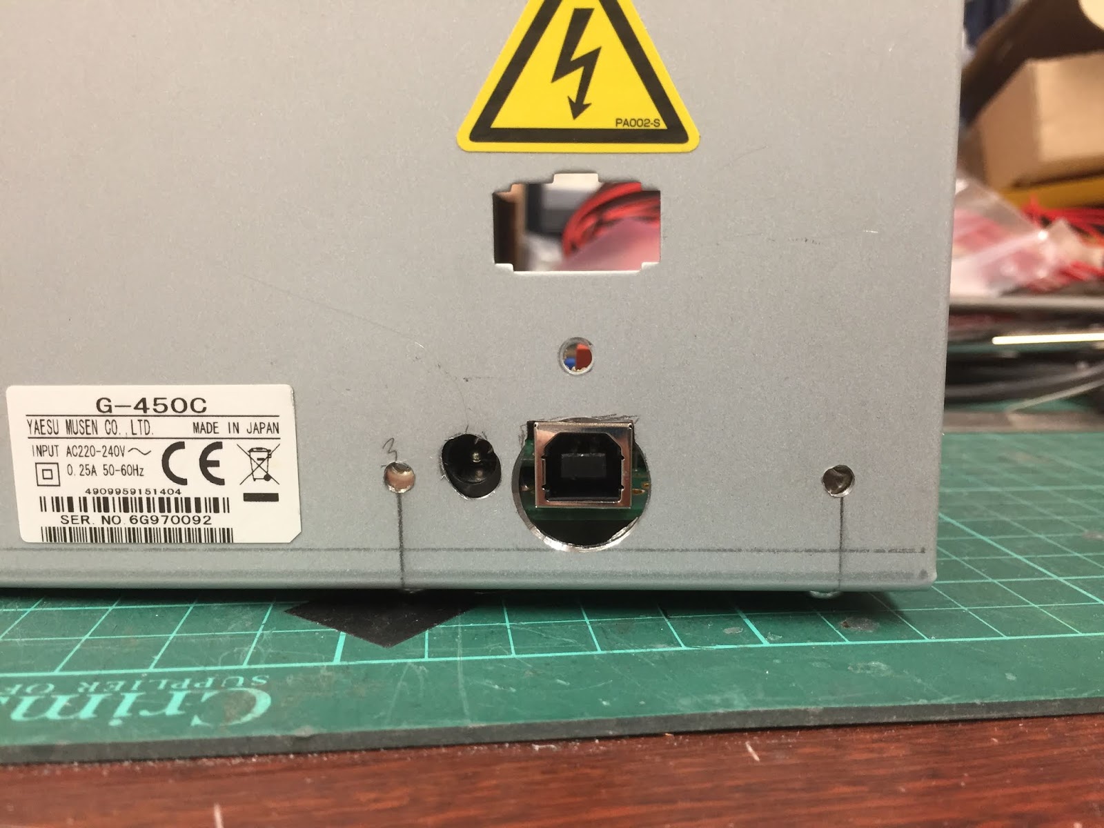
The rear of the controller box with the holes cut for the DC power
and USB connector.

Now you can see from the above picture the holes didn't quite align horizontally and this was down to me being a wally and instead of adding a couple of millimetres to the template I did the opposite and removed a couple of millimetres instead, so had I carried out that operation successfully everything would have aligned.   I still ended up with yet another problem shown below.

ERC fitted within the original rotator controller.

If you look at where the PCB stand offs are in relationship to the case fixing holes in the chassis even though there is enough height clearance so that the screws do not foul on the underside of the PCB what I hadn't taken into account was the fact the case wraps around the chassis when screwed together, this meant I needed to mount the PCB using only the two PCB mounts towards the middle of the chassis.   Now this is in fact fine the board isn't being put under any stress though these mistakes are annoying no one will be able to see them.

The original rotator gubbins replaced and the ERC cables attached.

I then replaced the front panel, power supply and original controller board with this done I could strip some insulation off halfway along both the brown and white wires this is so the ERC can be placed in parallel to the rotator and Yaesu controller to measure the feedback voltage which keeps track of the beam heading.


The control button side of the controller. 

Now the tricky part is to connect the blue and black wires from the ERC controller on the original controller heading controls these switches already have a couple of quite thick gauge wires attached to them and attaching the new wires along with the originals is a bit of a pig but if you start with the switch nearest to the mains transformer it's not too bad.

With the ERC controller connected you can refit the outer case and reconnect the unit the rotator and plug the controller back into the mains and station DC power supply you can then move on to calibrating the unit.

On the software CD you'll find two pieces of software one to calibrate the unit and another to control the unit with.  

The calibration is a little bit more involved for the Yaesu G450C rotator in that you need to do an extended calibration.   This involves calibrating at more headings than would be normal.   The general gist of the procedure is to start the calibration software as shown below.

Calibration Software
Once you have set the controllers com port, which you find in the Windows device manager, you'll be able to read the ERC memory.   Next you need to set the rotator fully counter clockwise, using the Yaesu controller, once set to 0 degrees you can perform an extended calibration by using the "Extended 1" function which measures the rotator feedback voltage at 30 degrees intervals once each interval has been measured the software will tell you to advance to the next calibration point.  

A point to be aware of is make sure when you are setting the Yaesu controller that you look straight on to the Yaesu controller heading indicator otherwise you can calibrate to the wrong heading.  

Once the calibration has been completed close the calibration software and start the rotator control software shown below.

The control software supplied with the kit.
Once the rotator control software has started remember to set the com port and wait few moments for the software to connect.   Now click on a point on the compass and the rotator should start to turn to the position you selected and check the Yaesu controller agrees with the software, try this a few times to confirm the calibration if the calibration is off you'll need to repeat the calibration again.

Though the supplied software is ok it's very basic and in fact I replaced with PstRotator from YO3DMU it's an excellent piece of software and though you need to pay 20 Euro's for the licence it's a bargain and I wouldn't use anything else.  The software can set with presets for quick heading changes, you can open a map and click at any point and the beam moves to that head, the other nice feature if you live near the coast is have the beams turn into the wind when the wind speed exceeds a threshold of you choice.

PstRotator

This is one of those projects that starts off as a 'nice to have' which turns into 'how did I ever manage without it' I'm sure no one would regret adding the ERC to their rotator controller.


Wednesday, 3 October 2018

2m Antenna Update

After spending next to four weeks off the air due to the new antenna system suddenly going high VSWR 6:1 the guys, Dave and Fred, finally managed to get the system down for us to check where the fault lay typically when I test the VSWR before taking it down the fault had cleared on its own.

Originally the system gave a VSWR of 1.1:1 until it rained when it went high, now since that point it hasn't rained so I can only assume during the intervening period whatever had got damp had since dried out.

All the connectors looked dry with no indication of water ingress seen, the coupler was also bone dry.   The powabeams use an ABS moulding to fix the driven elements to the beam and this is glued shut during manufacture so it's impossible to open without destroying the moulding in the process.

We put more rubber sealant on around the Powabeam ABS moulding, the end caps on the coupler and around the N-Type sockets on the coupler as well I also wrapped self amalgamating tape around the ends and over the centre hole that gives access to the middle socket.

We then put the system back together with all joint resealed with amalgamating tape it now looks like it should take being dipped into the sea before it leaks but only time will tell.

The only modification we made was to make the quarter wave chokes as depicted on the Powabeam website originally we put the loop over the back of the beam which certainly worked however both Dave and I have Powabeams and switched the recommended way of creating the choke which we both agree seems to give a better response.

I used the system again in this weeks 2m UKAC and it worked flawlessly so fingers crossed it'll carry on working.

Again a big thanks to Dave M1DNJ and Fred for doing all the manual labour.

Tuesday, 18 September 2018

DCI-145-2H 2m Filter.

I recently swapped an unwanted Daiwa VSWR meter for a DCI-145-2H 4 pole bandpass filter for 2 metres.   I don't really need it however I have on the odd occasion thought it might help with some strong out of band signals that occasionally pop up so swapping an unwanted piece of equipment for a piece that might be useful I thought was a good deal.

DCI quote the following specification.

Centre Frequency : 145MHz
Band Width : 2MHz
SWR : < 1.3:1
Return Loss : >18dB

DCI measure the filter response at the following intervals.

135 MHz : -72.650 dB
140 MHz : -46.450 dB
145 MHz : -0.755   dB
150 MHz : -42.981 dB
155 MHz : -65.548 dB

Out of pure interest I thought I see what I measured the above as using the DG8SAQ VNWA.

Filter response etc measured with the VNWA.
As you can see the filter specifications for SWR, RL as described the only difference is with the filter skirt readings being slightly off but in quite good agreement with DCI which I'll assume used a slightly better VNA than the one I have. ;-)

Saturday, 8 September 2018

New 2m Antenna Is Finally Installed.

With the help of my nephew Fred and Dave M1DNJ I've finally got the two new Powabeam 9 ele CQM's installed, see my previous post for specifications.

Fred got the job of taking down the original system which consisted of a single 9 ele LFA from InnoAntenna this antenna has worked faultlessly and in fact I only switched to the CQM design due to weight, I don't have a tilt over mast so the stub needs to be lifted into place with the top beam as well as the coupler and 70cm beam by hand not a easy task while standing on a ladder, the LFA even survived being dropped into a hedge from 8m with the rotator and mast attached when the guys from MM0CUG took the antenna down before fitting it to the new mast.

The original 2m LFA with a 70cm 12 ele above.
The first thing to do was remove the original antennas Fred duly got on the steps and disconnected the antenna tails and loosened the rotator stub clamps.

Fred disconnecting feeder and loosening clamps
With antenna removed Fred G-Clamped the new rotator cage to the garden bench and fitted the rotator and thrust bearing which we both proceeded to align. 

Rotator, Thrust Bearing Fitted and Aligned. 
With the rotator and bearing completed Fred got on with the task of fitting all 18 parasitic elements as well as the driven elements to the booms ready for installation.

Fred with set square fitting the parasitics.

Dave M1DNJ and Fred along with Amber then got on with fitting the rotator cage including stub mast, top beam, power coupler and 70cm to the mast thank the gods Fred has good arm strength and a taste of heights.

Stub with top beam, 70cm beam and cage fitted.
Next up was fitting the bottom beam to the mast. 

Bottom beam being attached to stub.
And finally connecting up the bottom beam to the coupler and jobs a good un. 

Coupler connections all done.
And lastly fixing the cables to the mast.

All most done.
Hurrah the finished system finally raised.

The new system raised.
The system gives an VSWR of 1.1:1 @ 144.300MHz with a resistance of 45ohms and reactance of 2 ohms.  

I must give thanks to Dave M1DNJ, Fred and Amber putting up with me trying to run them over with the wheelchair while I fretted over various bits and pieces.   I've been told I'm quite OCD about my antennas. ;-))

UPDATE : 6th September 2018 --   Well the first hard rain since putting the antenna up and the SWR has shot up to 6:1 oh bother this means sadly I'll be off 2m for awhile until I can get the antennas down and workout where the water has got, I suspect the Powabeam driven element ABS moulded fixing block which I had heard can give issues I thought I had sealed it up with extra sealant but obviously not!

Friday, 10 August 2018

Kuhne Electronics IC7300 IF Transverter Mod Board - Update

I recently fitted the Kuhne IF transverter modification board and found I had some issues with it.

When I first fitted the board I had a strange pulse appear on receive when using the transverter I original put this down to having to much signal going from the transverter to the rig and so switched on the rigs attenuator to resolve the issue.   Now I didn't do this in a very scientific manner I just put the attenuation in on gut feeling.

Next I noticed when using my Wavenode power meter when I de-keyed the transmitter I had a 1.3W RF spike out of the transverter which resulted in a 200W spike from the linear.   After pulling the system apart in an effort to resolve the issue I discovered the cause was the Kuhne modification.

As I found the issue with the Wavenode was caused by the interface board I had another look at the RF pulse I was seeing without the rigs attenuator turned on.   I tuned in the GB3VHF beacon which appeared as S9 on the S meter while using the transverter with the combiner and then switch back to IF interface where GB3VHF stayed at S9 without the rigs attenuator turn on however the pulse was present again so I again switched the attenuator back on resulting in the beacon losing an S point but the pulse had disappeared.

I did a quick search on the internet and found on the IC7300 io.groups reflector a PDF documenting a modification to do with instabilities found with the IC7300 power amplifier when the Kuhne board was disengaged and carried out the modifications which made no difference to my problems which in all honestly wasn't surprising.

I've now decided to remove the modification and go back to the combiner and attenuator method of driving the transverter which was far more stable and had no issues.

Another observation is the fact I kept seeing some IM products in the adjacent 3kHz from where I was operating from which I just couldn't get rid of it wasn't bad about -25dB in relation to output and wasn't always present but with the modification removed it vanished completely to the point where any IM product is now at least -35db at worst.

Wednesday, 18 July 2018

2m Antenna Upgrade.

I current have a single 9 Ele LFA from G0KSC and though I have no complaints regarding the antenna I'm now at a stage where the only place I can make a sensible improvement in my 2m setup is to replace the antenna.  

I would have liked, probably like most amateurs, to have more the space to put in an array of four 9 element antennas however this isn't practical on my property.  

Now I would like to give EME ago at some point but I don't have elevation available so this put me in a quandary how to improve the system why still allowing myself a little bit of freedom to still carry out a few EME and Meteor Scatter communications when conditions allowed but also give me a better score in the RSGB 2m UKAC as well as general tropo, E's etc QSO's.

I had a chat with few local amateurs I discovered one of them M1DNJ has a similar setup to myself but has a better antenna and mast setup after numerous discussions with David I decided I go with a 9 Element G4CQM design made by Powabeam antennas a CQM9C4 as the performance looked to be about the same as the LFA but with the bonus it's lighter in weight so would make lifting on the mast much easier to accomplish as I don't have a tilt over.   I decided to go with a of two stacked Yagi's.

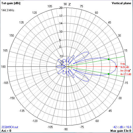
Richard at Powabeam has published the specifications for a single Yagi as well as a quad array but I couldn't find the specifications for a stack of two so decided to run the simulations myself.  I'm not going to go through all the figures and configuration that can be deduced from the Powabeam website and the images below.

4nec2 - 3D - 2 x CQM9C4

Total Field - 2 Stacked CQM9C4
Horizontal Plane - 2 Stacked CQM9C4

Verical Plane - 2 Stacked CQM9C4

TANT - CQM9C4 - 2 x Stacked Array.


Tuesday, 17 July 2018

2m quarter wave coupler

I'm just about to update the 2m antenna system moving from a single 9 element LFA by G0KSC to two 9 element CQM9C4 Powabeams stacked.   To stack the two yagi's you need a coupler to join to the them together.

A quick search on the net I came across two ways of doing this one based on using coax and the other using aluminium box section with a 15mm copper pipe forming a square piece of coax.

You can buy a ready made coupler but I so happened to have a piece of aluminium box section of the correct length as well as a piece of 15mm copper pipe and three N-Type laying around so I though I'd see if I could save myself £70 and build one myself.  

The way to work the dimensions you use a piece of software called appcad this will allow you to calculate the length of the inner copper pipe which turns out to be 520mm for my size of aluminium box I followed the design for the two port coupler from DG7YBN's website.

What I found was the length isn't particularly critical but the distance between the copper tube running thought the box section is my ali box has an inner dimension of 24mm and as mentioned before the copper pipe is 15mm which requires a spacing of 4.5mm to obtain this I wound insulation tape around a screwdriver until it conformed to the 4.5mm and then used this to centralise the tube in the section.  

An afternoon with the hacksaw and drill press I had the basic coupler built and I ten minutes with a 100W soldering iron had the copper tube soldered to the N-Type sockets.

I tested the coupler on the VNA and got a return loss of around 25dB and a VSWR of 1.1:1 which is near enough so I'm a happy bunny.

I'm still awaiting the materials to build the powabeam yagi's but I'll post again with the build and how they went together.

2m Quarter Wave Coupler Results @ 144.3MHz


Sunday, 8 July 2018

Vine 6M4DX


A few weeks ago a message came up on my radio club message board offering a Vine 6M4DX 4 element 6m beam for sale, now I've not worked much on 6m and in truth I don't tend to working on anything other than 2m and 70cm but the antenna was cheap £40 pounds so I emailed the seller Colin and bought the beam.  

Now I wasn't holding out for much as it's a secondhand beam but upon picking the beam up I was pleasantly surprised as the beam came in the original box and been taken down and packed away with the bits marked and fitting placed into plastic bags, happy days.

I thought that the beam was missing any instructions and I was unsure of how to fit the hairpin match so emailed the manufacturer which I discovered had ceased trading in 2016 but there website is still present with an email so I emailed them not expecting a response.    To my utter surprise Ron at the aforementioned company emailed me back with 12 hours with all the specs and fitting instructions  which I thought was amazing and I only wish some companies that are trading could match this defunct companies customer support. 

The Vine 6M4DX has the following radiation pattern. 

6M4DX Radiation Pattern
I also managed to pick up for free an older rotator and controller so this would get me QRV 6m for next to nothing from a friend of mine so even more happy days.

Here's my nephew Fred and my mate Mal G1NOX
baking in the sun putting the beam together. 
It took Fred and Mal about 4 hours to construct the beam and get it up on the chimney.

The completed beam up on the chimney stack

When I tested the VSWR the beam gave less than 1.5:1 across the whole 6m band which is fine for my purposes.  

Now typically once the beam was up the rotator controller died within 5 minutes, oh bother so I need to fix that before I can the beam a full work out.  But all in all a great bit of kit for peanuts and gets me active on 6m.